ECU Test Points, Diagnostics and Specifications
#Test Points and diagnostics for Land Rover 3.9 ECU
Original from http://www.landroverclub.net/Club/HTML/ECU_check.htm
ECU's on Fuel Injected Engines
at the example of the 3.9 Range Rover engine
Sorry for the sometimes not absolute correct names, text translated from french
This procedure should be similar on any engines using an flap for measuring the air flow. Those who use Lucas ECU box and an Hot Wire to monitor air flow are slightly different. We used this procedure successfully on many different cars. But it's at your risc. And you may well damage a component beyond repair if you screw it up.
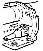
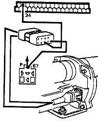
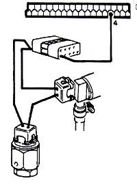
Connectors and Sensors
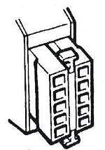
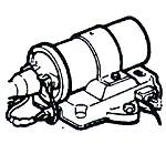
 Connector to the ECU
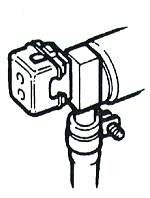
 Timed thermal contact
 Cold start enrichment
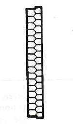
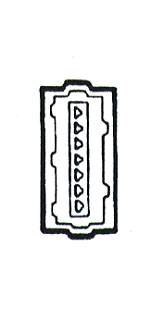
 Resistance box
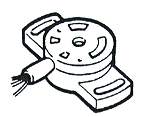 Flap position sensor
 Constant energy coil
 Air flow sensor connector
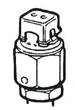
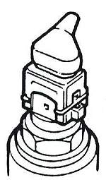 Coolant temperature sensor
 P= pump relay M=main relay S=steering relay
 Air mixture valve
Feeding of the electronic regulator
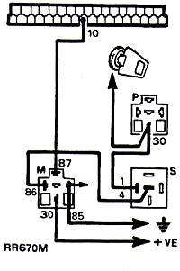
(This is the ECU box)
- Connect Voltmetre between Pin 10 and ground. Contact.
- No reading: Check cables and connectors, check Main relay by substitution of a new unit (this is genuine LR instructions...)
- Lower than
11 V: Check cables and connectors for a bad or corroded contact
Normal result: 11-12.5 Volts
Fuel pump contacts
- Connect Voltmetre between Pin 20 and ground. Contact. Air flap closed
- When closed: Something else than =V when flap closed: check switch on air meter (flap) housing
- When moving: No reading: Check wire harness from relay to air metre, then from air metre to relay of fuel pump. Check the relay by substitution of a new one. Check the pump by connecting a wire directly from battery + and - to the pump
Normal result: 0 V when closed, 11-12.5V when flap moving
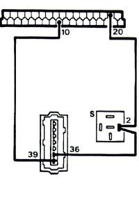
Starter rotation signals
- Connect Voltmetre between Pin 4 and ground. Turn the engine over with the starter.
- No reading but starter turns: Check wiring harness from ECU to relay and electronic regulator
- No reading and starter does not turn: check starter and starter relay.
- Reading under
8V: check batterie (connect another one) and starter
Normal result: 8-12V
Air metering valve
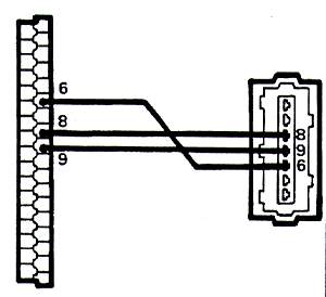
-
Connect Ohmmetre:
between Pin 6 and 8: 360 ohms between Pin 6 and 9: 560 ohms between Pin 8 and 9: 200 ohms
-
Differing values: check cables with ohmmetre, check air metering valve but make sure it's completely closed.
Normal result: above values + 10 ohms
Water temperature sensor
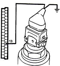
- Connect Ohmmetre between Pin 13and ground
- Differing values: Check cables and connector, change sensor if readings still differ
- Take only short readings as sensor may be damaged by heat from curent from ohmmetre
Normal result:
-10°C = 7-11,6 kohms

+20°C = 2,1 to 2,9 kohms

+80°C = 0,27 to 0,39 kohms
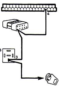
RPM signal
- (constant energy ignition)
- Make a connestion between - of the coil and Pin 1. Connect voltmetre between Pin 1 and ground
- No reading: check the connectors between coil and regulator
Normal result:Fluctuates between 6 and 9V
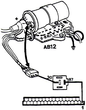
Injectors
Injector 7
- Connect ohmmetre between Pin 14 and 87 of main relay
- Reading below normal: Disconnect one after another the injectors until you find the one with low or 0 resistance. Replace.
- If all are OK you must check the wiring harness and connectors as well as the resistance bloc
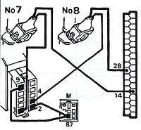
Injector 8 Connect ohmmetre between Pin 28and 87 of main relay
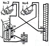
Injector 2 Connect ohmmetre between Pin 31 and 87 of main relay
Injector 4 Connect ohmmetre between Pin 30and 87 of main relay
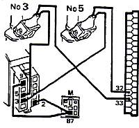
Injector 3 Connect ohmmetre between Pin 33 and 87 of main relay
Injector 5 Connect ohmmetre between Pin 32 and 87 of main relay
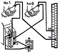
Injector 1 Connect ohmmetre between Pin 15 and 87 of main relay
Injector 6 Connect ohmmetre between Pin 29 and 87 of main relay
Normal result: Between 7 and 10 ohms
Injection ramp
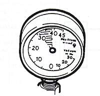
- Mount the manometre on the flexible line to the cold start enrichment injector. Contact and move the air flap to close the electric circuit of the fuel pump
- Pression 0: Check if fuel pump gets 12V, if not so replace the relay of the pump and then the main relay.
- If the pump gets 12 V check it's ground (a common fault) by laying a wire directly to the ground. If it still does nothing chances are good the pump is shot. Take it out and check it again on the bench.
- Pression out of limits (above or below): Check for leaks on the complete circuit, coloring around line connections and leaking injectors, then pressure regulator and anti-return valve- in this order.
Normal result: 2,4 to 2,6 kg/cm2
Air Mixture Thermovalve
- Possible fault:
- Connect ohmmetre between Pin 34 and 87 of the fuel pump relay
- No reading: Check wiring and connectors between fuel pump relay and air mix valve as well as electronic regulator. Than disconnect valve and check it by ohmmetre
Normal result: 30 - 40 ohms
Cold Start enrichment injector
- Possible fault:
-
- Disconnect timed termocontact.
- Successively ground the wires.
- Connect ohmmetre between Pin 4 and ground
- No reading: Check wiring and connectors between ECU, cold start injector and temporised thermocontact.
- Cut off: Check wires, connectors and cold start injector
Normal result: 0 - 5,0 ohms
Air temperature sensor
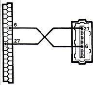
- Possible fault:
- Incorporated in the air flow sensor
- Connect ohmmetre between Pins 6 and 27
- Take only short readings as sensor may be damaged by heat from curent from ohmmetre
- If Reading unlimited:
- disconnect flow meter,
- connect Pins 6 and 27.
- If reading is now 0 the sensor is faulty.
- If reading still unlimited check wiring and connectors as well as ECU connector
Normal result:
-10°C: 8,26 to 10,56 kohms

+20°C: 2,28 to 2,72 kohms

+50°C: 0,76 to 0,91 kohms
Air flap position sensor
- Possible fault:
-
- Set multimetre on TENSION, reconnect ECU, contact
- Measure tension between green (-) and yellow (+) by the back side of the connector block near the ECU. Values should be:
4,3 (+- 0,2V). Lower or 0: check wiring and connectors
- Measure tension between green (-) and red (+) by the back side of the
connector block near the ECU. Values should be:
0,325v (+0,35v). Loosen screws and rotate sensor until reading is correct - The tension must grow progressively in the same manner as you open the
air flap.
Progressive from 0,3 to 4,5V - If the reading jumps or fluctuates you must change the sensor.
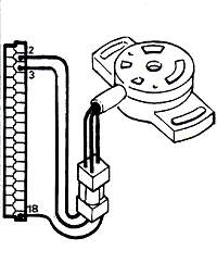
Deceleration shut off relay
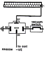
- Possible fault:
-
- Disconnect the wire from coil to relay.
- Contact off.
- Connect ohmmetre between Pins 1 and 30 of the relay. Unlimited is correct. Anything else: Check wires and connectors, then replace relay by a new one.
- Contact. The resistance must drop to 0. Anything else: Check wires and connectors, maybe even the vacuum switch.
- Repeat the measurement at least once.
Air flow sensor
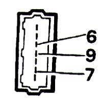
- Possible fault:
-
- Reconnect ECU.
- Contact.
- Pull back the rubber sleeve on the connector.
- Connect voltmetre between Pin 6 (+) and Pin 9 (-)
1,55V (+- 9,1V)This figures from the genuine book but I strongly suspect a fault here. I think it should read+-0,1V
- Connect voltmetre between Pin 9(-) and Pin 7(+)
3,7V +-0,1V - Open the flap slowly: The tension must drop
1,6V +-0,2V - Abnormal results: Change the sensor
Air flow sensor
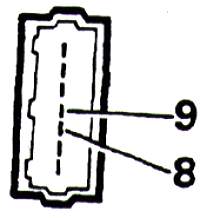
- Possible fault:
-
- Disconnect ECU.
- Contact.
- Pull back the rubber sleeve on the connector.
- Connect voltmetre between Pin 8 (+) and Pin 9 (-)
- Abnormal reading: Change sensor
- Normal result:
4,3V +- 0,2V